Design Proposal Case Study: Compact Li-Ion Battery Design for Outdoor Surveillance Equipment
SUMMARY
Excell Battery solved three critical challenges for a surveillance equipment manufacturer requiring a custom 15Ah Li-Ion battery pack for outdoor cameras: enabling safe charging in sub-freezing temperatures (with a self-heating system), delivering prototypes in an accelerated 8 week timeline (by prioritizing standard components over custom development), and supporting global manufacturing operations (leveraging Ultralife Corporation’s international production network for localized battery supply).
The resulting 3S3P 21700 cell configuration with integrated 12W polyimide heater extends Li-Ion charging capability from the standard 5°C minimum down to -20°C ambient conditions, while the accelerated development approach and global manufacturing support provide competitive advantages for the OEM’s international operations.
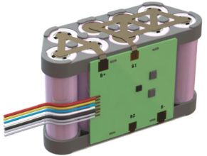
Table of Contents
1. PROJECT OVERVIEW
The Challenge (Real Problem)
A surveillance equipment manufacturer required a battery solution for their next-generation camera system. The project presented three critical challenges that demanded innovative engineering solutions and strategic manufacturing approaches.
Primary Engineering Challenges & Solutions:
1. Cold Weather Charging Capability
- Core Problem: Li-Ion batteries cannot be safely charged below freezing temperatures, however, battery needs to be able to charge in freezing conditions while maintaining safety standards.
- Operational Requirements: Discharge operation from -20°C to 60°C, but charging limited to 5°C to 45°C without intervention
- Solution: Integrated 12W polyimide heater powered by the battery’s own stored energy to warm cells above 5°C charging threshold, enabling safe charging in -20°C ambient conditions. See DESIGN SPECIFICATIONS section for more.
2. Accelerated Development Timeline
- Core Problem: Prototype delivery needed in 8 weeks vs. typical 6-month development timeline
- Operational Requirements: Fast time-to-market prioritized to meet competitive positioning
- Solution: Prioritized proven, off-the-shelf components (standard fuel gauge/protector IC with I2C interface) over custom firmware development to reduce design risk and validation time. See SYSTEM INTEGRATION, MANUFACTURING, AND REGULATORY STRATEGIES section for more.
3. Global Manufacturing Requirements
- Core Problem: OEM manufacturing operations across multiple international locations
- Operational Requirements: Battery production needed to be localized near final device assembly sites
- Technical Constraint: Solution must support distributed manufacturing while maintaining consistency
- Solution: Leveraged Ultralife Corporation’s international manufacturing network to enable localized battery production with reduced shipping costs, lead times, and supply chain complexity. See SYSTEM INTEGRATION, MANUFACTURING, AND REGULATORY STRATEGIES section for more.
Additional Technical Constraints:
- Space Limitation: Maximum envelope of 3.5″ × 2.5″ × 5.1″
- Power Demands: 15Ah capacity, 3A nominal/6A peak discharge current
- Regulatory Compliance: UN38.3 transport and IEC62133-2 safety standards
Solution Approach
System Architecture: 3S3P Li-Ion configuration using 21700 cells
Key Components:
- 9× 5.0Ah 21700 cells (3.6V nominal)
- fuel gauge/protector IC
- 12W polyimide thin film heater with PTC thermostat at 55°C
- Custom molded support frames in trapezoidal layout
Target Specifications:
- Capacity: 15Ah at 10.8V nominal voltage
- Compact Design: Estimated dimensions approximately 3″ × 2″ × 4.75″
- Operating Range: -20°C to 60°C discharge with integrated heating
- Communication: I2C interface for system integration
2. DESIGN SPECIFICATIONS
Cell Selection and Configuration
Component Specifications:
- Cell Type: 21700 format
- Individual Capacity: 5.0Ah @ 3.6V nominal @ 0.2C discharge rate
- Configuration: 3S3P (3 series, 3 parallel)
- Voltage Range: 7.5V minimum to 12.6V maximum
Design Rationale: The 21700 format was selected to meet the capacity requirements within the space constraints. The 3S3P configuration provides the required 10.8V nominal voltage while achieving 15Ah capacity through parallel cell arrangement.
Innovative Mechanical Layout
Trapezoidal Cell Arrangement: The design employs a trapezoidal layout rather than conventional rectangular arrangement to optimize space utilization within the dimensional constraints.
Implementation Details:
- Support Structure: Molded plastic support frames ensure proper cell spacing
- Interconnect Strategy: PCB placement on one side of the cell assembly with direct tab connections
- Housing: Molded cell frames with PVC shrink covering
- PCB Integration: Side-mounted PCB retained by support frames
Integration Considerations: The trapezoidal layout enables the heater element to contact the sides of all cells for thermal management.
Battery Management System Design
Core IC Selection:
- Interface: I2C/SMBus compliant communication
- Functions: Fuel gauging and protection
- Development Advantage: Standard interface reduces development time compared to custom MCU firmware
Serial Number Handling: The customer’s serial number format exceeds the standard 2-byte SN register capacity. Solution approach includes storing the serial number in Manufacturer Info registers (32 bytes available) or separate EEPROM on the same I2C bus.
Self-Heating Thermal Management Strategy:
- Core Challenge: Li-Ion batteries cannot be safely charged below 0°C, limiting outdoor operation
- Innovative Solution: 12W polyimide heater powered by battery’s own stored energy brings cells above 5°C charging threshold
- Operating Temperature: Discharge -20°C to 60°C, charging 5°C to 45°C (extended to sub-freezing operation via self-heating)
- Protection Strategy: Hardware-based PTC thermostat provides primary thermal protection independent of software control
3. SYSTEM INTEGRATION, MANUFACTURING, AND REGULATORY STRATEGIES
System Integration
Communication Protocol: I2C interface provides battery monitoring data to the host system. The component selected offers standard SMBus protocol implementation with comprehensive documentation.
Development and Manufacturing Approach
Prototype Strategy:
- EVT Phase: 3D printed plastic frames for rapid prototyping (50 samples estimated)
- DVT Phase: First injection molded parts to validate tooling (300 samples estimated)
- Component Risk Mitigation: Early component ordering ahead of design completion to address lead time challenges
Accelerated Development Timeline:
- Mitigation Strategy: Prioritized standard, proven components over custom development to reduce design and validation time
- Risk Management: Early component procurement with customer approval for design changes
- Component Strategy: Selected established ICs with comprehensive documentation rather than custom firmware solutions
Global Manufacturing Strategy:
- Solution: Ultralife Corporation’s global manufacturing network enables battery production near final assembly sites
- Advantages: Reduced shipping costs, shorter lead times, and simplified supply chain management for international operations
- Scalability: Consistent battery specifications maintained across all manufacturing locations
Regulatory and Safety Considerations
Safety Standards Compliance and Testing:
- Testing Strategy: UN samples built with first molded plastics to avoid schedule conflicts
- UN38.3: Transport safety requirements. 16 samples required for transport certification.
- IEC62133-2: Battery safety standard. 30 samples required for safety certification.
- Additional: Customer responsible for FCC, NDAA, RoHS, TAA compliance
Design for Safety:
- Enclosure Requirements: Battery enclosed within end device, not end-user accessible
- IP Rating: Applied to product as whole; battery itself does not require IP rating
- Cell Qualification: 21700 cells specified for 800 cycles to 80% capacity at 0.5C charge, 1C discharge at 25°C
4. KEY CONSIDERATIONS
Design Decision Framework
Cell Format Selection Criteria:
- Capacity Density: 21700 format selected for optimal energy density within space constraints
- Availability: Current manufacturing parts with confirmed stock availability
- Qualification: No NRND (Not Recommended for New Design) or EOL (End of Life) parts used
BMS Architecture Decisions:
- Standard vs. Custom: Standard IC chosen to prioritize time-to-market over custom firmware development
- Communication Interface: I2C selected for balance of functionality and development speed
- Component Selection: All parts specified as currently manufactured with available stock
Common Design Challenges and Solutions
Space Optimization:
- Challenge: Fitting required capacity within strict dimensional limits
- Approach: Non-rectangular cell arrangement and side-mounted PCB placement
- Consideration: Outer frame dimensions can be modified from trapezoidal to rectangular for mounting requirements without changing internal cell layout
Cold Weather Operation:
- Challenge: Li-Ion performance degradation at low temperatures
- Solution: Integrated heating element with contact to all cells
- Safety: Hardware-based thermal protection independent of BMS
Development Timeline Pressure:
- Challenge: Component lead times vs. accelerated schedule
- Mitigation Strategy: Early component procurement with customer approval for design changes
- Risk Management: Components ordered ahead of final design validation
Key Technical Considerations
Thermal Design:
- Heater Sizing: 12W power level specified for application requirements
- Distribution: Polyimide film heater enables uniform contact with cell surfaces
- Control: PTC thermostat provides fail-safe protection at 55°C
Manufacturing Transition:
- Prototype to Production: 3D printed frames for EVT, injection molded for DVT/PVT
- Tooling Risk: Mechanical confirmation required early in EVT phase to enable tooling order
- Volume Scaling: Design accommodates estimated production volumes (1000+ PVT, 45,000+ annual forecast)
Development Investment Structure
Payment Schedule:
- Project Initiation
- Final Design Completion
- EVT Prototype Delivery
- DVT Approval
Considering similar battery design challenges? Contact Excell Battery’s engineering team for technical consultation on space-constrained, environmentally demanding applications.